Information About Our Capabilities
Optical Engineering
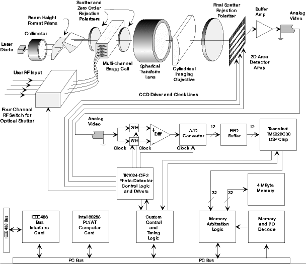
All aspects of the optical subsystem, especially its interface to sources and sensors, require specifications from the Optical Engineering methods. This includes optical source requirements for thermal and quantum sources such as radiance and irradiance specifications. For visual systems, the photometric values, given by weighting the spectral radiometrics for the human eye's photopic response, must also be considered.
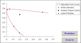
Further many visual systems rely on colorimetry, based on the standard observer's tristimulus values, to achieve full visual spectral response and accurate color balance for white color temperature requirements. Detectors also have spectral response curves that must be considered and modeled to ensure a product's performance. We use FRED Optical Engineering Software as well as proven MathCAD and Excel models to analyze and simulate optical subsystems from end to end.
Systems Engineering
Innovative developments must rely on comprehensive Systems Engineering. Systems engineering goes beyond radiometric and photometric requirements to include required electronics and signal processing functions. In addition to expected signal levels, systems engineering must also assess noise levels and issues. Thus systems engineering must include signal data formats, filtering and processing algorithms to ensure a product's performance.
Optical Design
The lenses in a system create the optical interconnect between source and sensor. Optical Design creates the lens prescription to meet system requirements. Lens designers come with vastly different methods and skill sets. But basically we all do the same thing. We don't design lenses as we use software that does the actual design iterations. What a lens designer does involves creating, designing, and refining the Merit Function used by the software. This "Merit" function is really a "Cost" function as higher values mean the design has higher aberrations and conforms less to other targets.
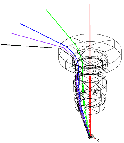
It is these "other targets" that really discriminate the designer's skill. All of the design programs have default functions for assessing the aberrations and lens performance. The additional targets and how they are defined give other very important aspects of the design. Some of these may be how the lens operates such as achieving a telecentric image condition or creating a distortion map that deviates from F*tan(theta) (image height is proportional to the focal length times the tangent of the object angle which is used for camera objectives) to an F*theta distortion map (image height is proportional to the focal length times the object angle used by most laser scan lenses). Other very important conditions pertain to the size, shape and sensitivity to alignment of the actual lens elements.
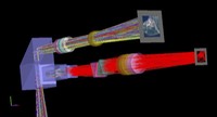
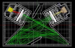
Other factors that may be involved in the design include multiple configuration (zoom) systems, athermalization, laser backflash, and Narcissus (for cooled Infrared systems). We generally use multiple configurations for athermalization with a configuration (or a set of configurations for zoom systems) to model the design over temperature. In these designs the choice of optical materials become restricted by their thermo-optic coefficients and Coefficient of Thermal Expansion (CTE). Ideally with the choice of proper materials, the design will not require thermal compensation over its operational temperature range. In the event that an air space must change over temperature, then that issue becomes a packaging constraint. Laser backflash involves a portion ot the laser energy that is reflected by an optical surface that may focus well on another surface. Even a very small fraction of the beam power can damage an optical surface if the focus is small and fluence (power density) exceeds the material's damage threshold. Optical designs that deliver high power and even pulsed low average power laser power must be assessed for backflash. This exercise becomes part of the design iteration as the design is adjusted to remove a potential problems and other problems occur. Narcissus analysis gets its name from the Greek hunter who saw his own reflection in the waters and fell in love with it. For a cooled Long Wave Infrared (LWIR) detector, Narcissus involves a reflection of the cooled focal plane array that falls on the a section of the array. All of the housing and optics will generate photons due to their uncooled temperature state. As long as the ambient radiation is uniform, it can be calibrated out of the image. A reflection of the image sensor onto a portion of itself will create a pattern that is not uniform and may reduce the sensor's dynamic range even if calibrated for its removal. Narcissus is handled very similarly to laser backflash. We will also verify and ensure an optical design is free of either or both of these nonsequential ray path issues using FRED Optical Engineering Software.
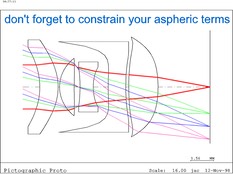
Beware the designer that uses default Cost functions and iterates until he gets a low number like playing a video game. These designers generally produce more expensive and even impractical designs that may image well in the design's analysis but for fall far short of a real value proposition in production. A very good designer knows very well how optics are fabricated, tested, and aligned. They have the experience to view a ray trace layout plot and quickly assess where the most sensitive surfaces occur and adjust the design to distribute sensitivity to other surfaces as needed (hint: any surface with a much larger ray deviation than others is a problem surface and will be very sensitive to fabrication and alignment errors). This experience allows that designer to add constraints that increase the yield and reduce the costs of production optics. Further, they are usually better equipped to generate dimensional tolerances and create element drawings that include all of the necessary information required by fabrication vendors to give cost estimates and shop procedures to produce quality optics.
Mechanical Design
The proper packaging of displacement sensitive components like lens elements requires experienced Mechanical Design. Other optical subsystems such as scan motors and other electromechanical devices require precision for stable mounts and housings. Unlike a compound lens in a single housing, the mechanical design for a complex optical system generally requires three dimensional (3D) layout experience. We use a combination of AutoCAD, as needed, and SolidWorks to complete these types of packaging designs. The advantage of AutoCAD comes from its highly accurate coordinate geometry based on absolute coordinates. Most optical design programs can create CAD files that can be imported to AutoCAD or SolidWorks. However in SolidWorks, lens elements can be accidentally moved until they are fixed in the assembly coordinate space. Also, the lens elements are dumb solid primitives and cannot be edited.
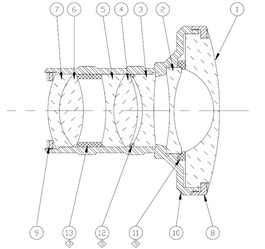
We take the exported CAD file from the design software with element and ray geometry and import it to AutoCAD which allows for additional folds (mirroring) to provide fitting for the design to a limited package volume. When the layout is complete, the AutoCAD geometry is then imported to SolidWorks to create one or more fixed reference sketches that can be used to design the opto-mechanical package by constraining solid parts to the master sketch(es). We have a set of SolidWorks generic optical elements that take the actual optical design values to create accurate parametric models of the lens elements and substations. This approach allows for changes in the element specifications that may arise without the need to start the package design from scratch.
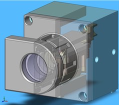
With the glass and reflective elements accurately modeled and placed, we then design the mounts and fixtures that support the optical elements. This process includes more that the design of lens barrels and optical benches. The design must be stable over a range of operating temperatures and survive a range of storage temperatures as well. We choose mounting materials for the CTE and the methods for mounting the glass to metal for the applications thermal requirements.
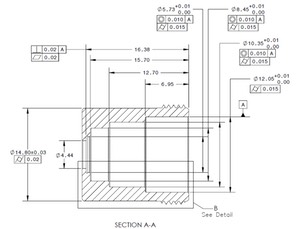
Further, these mounts and optical elements must support the precision required to meet the design's acceptable fabrication and alignment tolerances. To properly convey these tolerances, we use Geo-Metrics (Geo-dimensional Tolerancing) ANSI Y14.5-M. There are now three iterations of this widely used and extremely useful specifications. A common mistake regards a designer that fails to specify which version was used which is very important to their interpretation and is the cause of unnecessary litigation when dealing in volume optical production.